Words: David Lillywhite
Technology moves ever faster, but rather than being a threat to the world of historic cars, it can aid parts replacement, reduce costs and improve safety.
As the planet goes digital, should we simply take refuge in our analogue world of classic cars, stubbornly savouring delicious thoughts of carburettor tweaks, oil-stained Haynes manuals and the English wheel? Or should we embrace the changes and harness the power of digital to solve analogue problems?
What sort of problems are we talking? Most obviously, there’s the accurate, affordable creation of obsolete parts, from minor engine components to entire bodies. But there’s also digital archiving, to record the form of a valuable car or individual components in case of future accident damage, and the computer analysis of an engine that’s always been known for, say, overheating or blowing head gaskets.
In the same vein, aerodynamic modelling of an historic race car might reveal why it’s prone to leaving the track at high speed, or could simply aid a team or amateur driver learning how to set up such a machine without resorting to potentially dangerous experimentation on the track.
Welcome to the world of digital engineering, a huge boon for every age of car and for every genre of preparation and restoration. Its use in the historic auto world is a long way from being widespread, but we talked to one of the leaders in the field, KW Special Projects. The founders of this Bicester Heritage-based UK company started using digital engineering in early-1990s BTCC touring-car development, and the firm has since worked with Le Mans and Formula 1 cars, winter Olympics teams, cyclist Chris Boardman and even top-flight artists. More recently, its KW Heritage division has been applying the same expertise to historic cars.
Digital archiving
Let’s begin here, because it’s the centre point for all digital-engineering jobs and, as KW Special Projects co-founder Kieron Salter says: “By definition, digital assets don’t exist for classic cars.” In fact, until the mid-1990s, all engineering drawings were two-dimensional, either committed to paper or, from the 1980s-on, sometimes created using 2D computer-aided design (CAD).
Basic 3D CAD systems emerged in the car world in the mid-1990s, although it took a few years for such modelling to become prevalent. Trouble is, the original file formats of those early systems are generally no longer accessible, so a part of the work that, say, KW does is to work with old file formats, and also to ensure that more recent files are regularly updated and converted to contemporary formats, otherwise they’ll become useless. “You can’t keep a file for ten years then expect to use it, unfortunately,” says Kieron. “The information is still valid, but you have to keep opening it and updating it.”
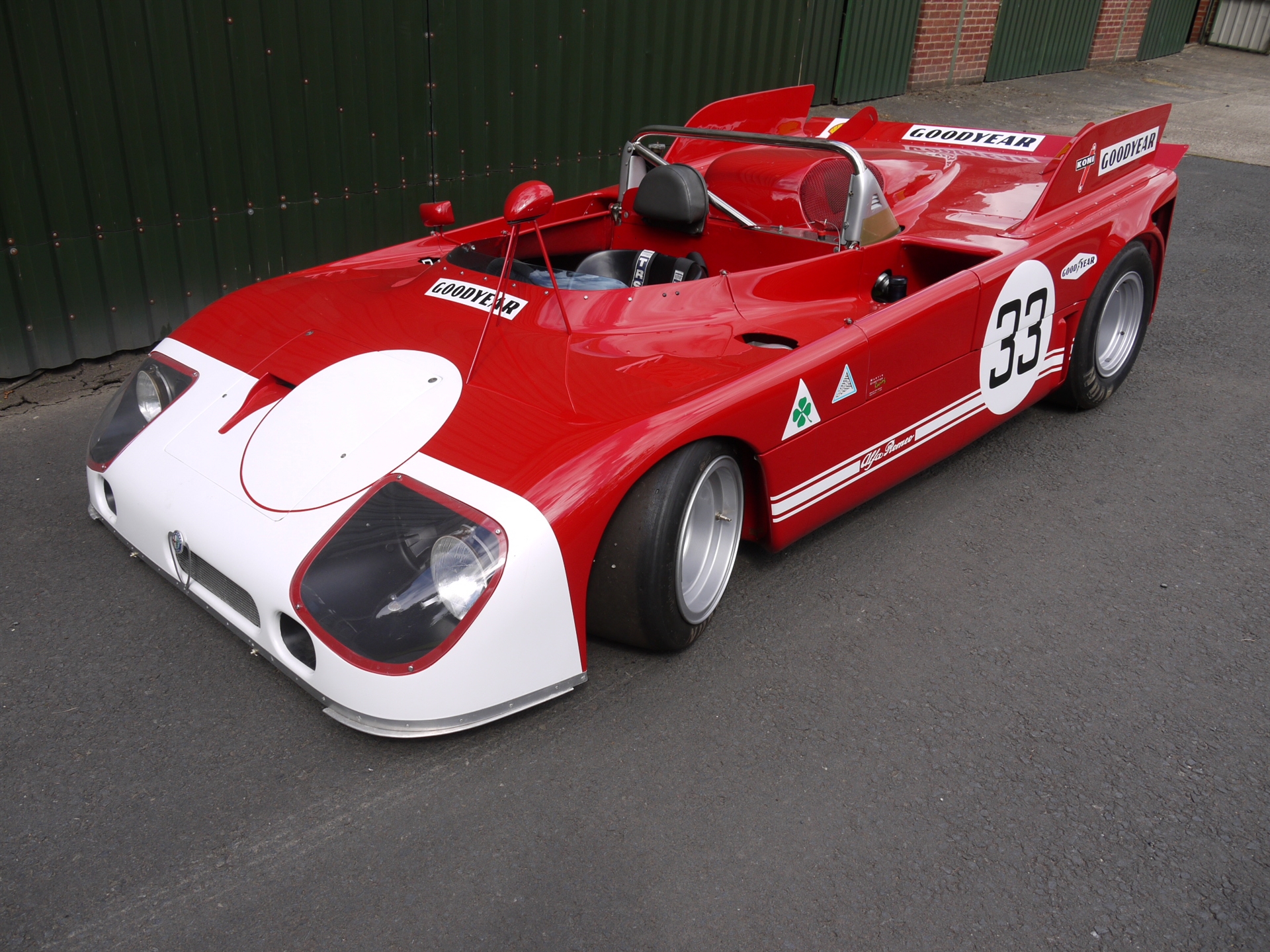
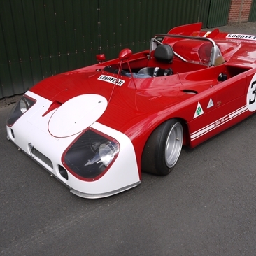
What about creating these digital assets in the first place, though, given that there never will have been a 3D CAD model of, say, a Blower Bentley’s supercharger housing, an Alfa TZ1 headlamp nacelle or a Porsche 917 suspension hub? That’s where scanning comes in…
3D scanning
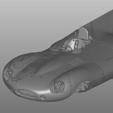
Imagine a 3D image of your car, or a part of your car, that can be turned around to any angle on the computer screen.
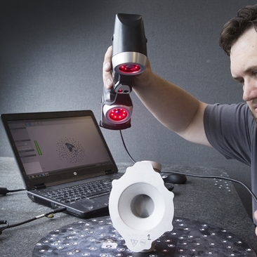
To achieve it, the vehicle or part in question is scanned by specialist equipment. This costs thousands – KW’s top-level hand-held scanner is around £50,000, for example, and there are also purpose-made car bodywork scanners available.
Using a hand-held unit for a smaller item, the surface being scanned has to be covered with adhesive dots. These are each set around 150mm apart on relatively flat surfaces, closer on more complicated shapes. From this, the scanner is used to take multiple ‘pictures’, ensuring that at least three of the dots are visible in every take, ideally in a triangular shape. For an entire car, this process takes a few hours. It’s accurate to 0.01mm over a square metre, or 0.04mm over a cubic metre.
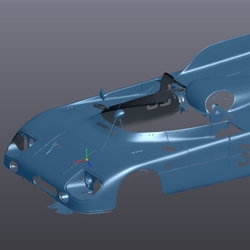
Using specialist software, these pictures are stitched together, the dots being used to create reference points to map the positions of each picture. The resultant information creates a Tron-style mesh file of the scanned item, which looks impressive but is actually quite useless without considerable further manipulation.
So now comes the interesting part: the process of creating a workable shape from the data produced. It’s worth noting that this process isn’t required until there’s a need to create a physical part from the data or to analyse the component in question – so the data could remain in this early form as a record of the car or component until further work is required, an insurance policy if you like.
If it is needed, the 3D data captured this far is digitally surfaced, to create a meaningful CAD model of the vehicle or component. This is a skilled operation, the first stage of which is auto-surfacing, which interprets the scan data and allows the engineer to create an accurate 1:1 scale 3D model of a high-enough quality for, say, a suspension arm but not necessarily for a curved body panel. From that point, there
are mathematical tools to progress towards what is known as A-class surfacing, but human intervention is still needed to create a digital model that appears realistic. The trick, particularly with bodywork models, is to translate the data into something that captures the light in the same way that the human eye sees it.
Within this art form, though, common sense and deep engineering know-how are also required. The scan may have picked up the edges of old decals or minor damage to a panel, so these need to be smoothed out. But what if the component is more badly damaged? How should it have looked? And can it still be produced in the form it was originally made?
Edward Smith, who heads the KW Heritage division, cites the case of a damaged engine cover, which incorporates a bearing and oil seal. The engineer working with the 3D model needs to research how the cover looked before it was damaged, and work out whether there are direct replacements available for the bearing and seal. Even if there are, should they be replaced with modern, reliable equivalents? And should the case itself be made stronger to prevent a repeat of the damage that had destroyed the original? Even for a simple part, deep engineering knowledge is needed.
An external scan of bodywork might not show the underside or ‘B surfaces’, either, such as any interfaces, the internal strengthening or the hinges. More work is needed to establish those. For a component, are there internal galleries that can’t be scanned externally? In some cases X-rays and CT scans, like those used in the medical world, may be required. They’re more specialist skills but might reveal crucial information.
Virtual modelling
Once that 3D CAD model is produced, there’s much that it can be used for. Two of the most useful tools that can be applied are Finite Element Analysis (FEA) and Computational Fluid Dynamics (CFD). Sorry about all the acronyms, by the way…
Finite Element Analysis allows the computer to take the 3D virtual model and analyse how it would react to real-world forces such as those encountered when cornering or braking, or the effects of fatigue through vibration. Imagine using that to work out why a component is failing, or if a replacement part you’re about to create will be strong enough.
CFD, meanwhile, is the computer modelling of airflow, heat or fluid flow around or through an object. It can even be used to model how molten metal will flow through a mould during the casting process, to ensure that the metal will be evenly distributed – and hence uniformly strong.
Once again, CFD is an incredibly useful tool, and Kieron has used it in the past to analyse why F1 and, particularly, Le Mans cars have been prone to flip up into the air, such as the infamous Mercedes incidents during the 1999 24 Hours.
Want to know why they do? Through CFD, it was found that with many cars, the problem came when they got out of shape, sliding sideways at high speed. With sloping sides and a flat floor, the shape the sideways-sliding vehicle presented into the airflow was that of an aerofoil or wing, so the car would generate unwanted lift as it slid further out of control… Through CFD, the solution was to specify a stepped floor into the regulations, in order to break up that crude wing shape.
As for the flying Mercedes, it was all about excessive suspension movement allowing the nose to lift over a peak in the track. This then created ever-increasing aerodynamic lift as the front gained ever-more height – until so much of the underside was exposed that the force of the air on the floor flipped the car right over.
For historic race machines, the 3D model can be manipulated to model the suspension height and spoiler adjustments that the cars allow in the real world. In their day, the teams would have been able to experiment with these settings, sometimes in a wind tunnel. However, there will be less chance to do so now, and less accumulated knowledge on how the car will react to changes – and what might cause it to become unstable. “Getting the set-up wrong can be a massive issue,” maintains Kieron.
For road cars, particularly those that have been modified, CFD can aid performance and stability – and you only have to look at Singer’s work with its Design and Lightweighting Study of the classic 911 to see the advantages that aerodynamic optimisation can bring. But CFD can also be used to analyse engine cooling by looking at the flow of air through the engine bay, or the cooling of other components such as the brakes, clutch or further transmission parts.
Creating parts
So all this goes towards the end product; making the required parts. This might be done by directly 3D printing (which is sometimes referred to as ‘additive manufacturing’) the required components, but more traditional manufacturing techniques can benefit from digital engineering as well.
3D printing is the technology of building three-dimensional objects layer by layer. There are a number of different methods: Fused Deposition Modelling builds parts layer by layer by melting plastic and extruding it; binder jetting uses ink-jet technology to deposit a binder fluid onto a layer of powder and building it up; Metal Laser Sintering or Selective Laser Bed Fusion uses a laser to melt a layer of metal powder to build up components.
It’s an incredibly useful tool to directly create one-off or low-volume parts without having to produce moulds, or to engage a foundry or injection-mouldaing specialist – but it’s also invaluable in making moulds that can then be used to create a product by more traditional methods.
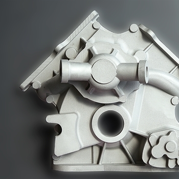
Consider an engine part that was originally cast alloy. It might well have been sand-cast – that is, creating a pattern of the shape required, using that to make a mould in sand and then pouring molten metal into the sand. But how about 3D printing the sand mould itself, direct from the CAD data of the component required? That’s now entirely possible, and saves a couple of labour-intensive steps in the process. If the shape of the component needs to be altered slightly, it’s much less work to alter or reprint the mould. The beauty is that the component will look the same as the original, because it will still be sand-cast in the same material.
Or think of those awkward hollow shapes, such as ducting or fluid pipes, that would normally have needed to be made in two pieces then joined, because the internal mould would otherwise be permanently stuck inside the object being produced. Now a male mould can be 3D printed in dissolvable material, allowing the component to be laid up in carbonfibre or glassfibre in one piece – stronger, less labour intensive – and then washed out of the component once it’s cured.
So this isn’t a way of replacing traditional manufacturing skills; it’s more about making those skills more accessible and affordable. This counts for panel making, too, because jigs and bucks can be more easily produced through 3D printing, and scan data can be used to ensure that the shapes produced are correct. There’s a real satisfaction in seeing high tech being used to enhance the use of the English wheel, for example – and that’s proving a great incentive for apprentices to get more involved with these traditional skills.
But, of course, 3D CAD models can also be fed into computer-controlled CNC lathes, milling machines and the like for more automated production of higher-volume components – once again improving accuracy and decreasing costs.
So the message is, don’t fear the new technology. We’ve not even mentioned the scanning of potentially weakened carbonfibre or the adaptation of obsolete engine-management systems – more of that coming soon – but it’s clear that if you harness digital engineering in the right ways, then cars that might have been left laid up through lack of parts or, worse, driven in unsafe states, can now be made usable and safe. Embrace the new!
If you liked this, then why not subscribe to Magneto magazine today?
Thanks to KW Special Projects, www.kwspecialprojects.com.